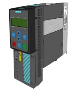
In this section we will introduce the low- voltage SINAMICS G120 inverter. You’ll learn about the main components, its structure, and receive some practice-oriented insight about the assembly and wiring of the frequency inverter. In this section we will introduce the low- voltage
Sinamics G120 PM 240, CU 240E-2 & BOP 2
Components
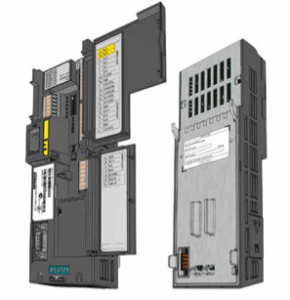
The SINAMICS G120 frequency inverter is modular. It consists of three basic components:
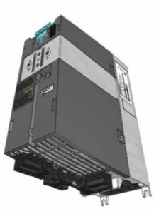
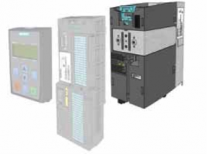
- Power Module ( Supply Voltage to The Motor )
The device is available in several sizes. Its power range is between 0.37 kW and 250 kW. The picture shows the PM240
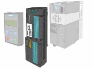
- The Control Unit ( Controls and Monitoring the Power Module )
There are various designs for the Control Unit. They differ primarily in terms of the control terminal assignments as well as in terms of different field bus interfaces. This tutorial will use the example of the CU240E-2 Control Unit. It was developed for stand-alone operation.
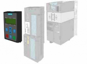
- BOP 2 ( Operate and Monitor The Inverter )
The basic input and display device is used to operate and set parameters for the inverter after being connected to the Control Unit. It is operated by pressing the buttons and features a simple commissioning thanks to the menu prompting and the two-line display (showing parameter and parameter value simultaneously).
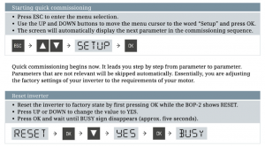
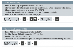
The following descriptions show how to set up the drive using the quick commissioning wizard integrated in the BOP-2.
Entering motor data
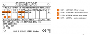
The values for the next parameter settings can be found on the rating plate of your motor.
Please set the motor data parameters according to the picture below.
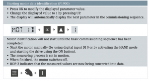
Motor data identification
After entering the motor data, the wizards asks you to activate the motor data identification. Motor ID is recommended for a live verification and optimization of the data that you have entered. The motor data identification initiates a “measurement” of the connected motor. In the process, the data previously calculated in the inverter is compared to the actual motor data and they are adapted to one another.
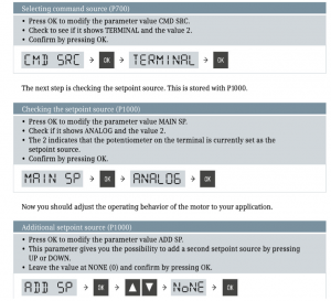
Command source, setpoint source, and application parameters
With the next step, you can select whether the Basic Operator Panel or the terminal should be the command source (parameter P700). In the case of the CU240E-2 being used here, the terminals are set as the default for the command source
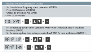
Next Parameter
The values are displayed in seconds. In both cases, the times indicated should not be too short, because this might result in an alarm.
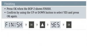
Finishing
You have now reached the end of the quick commissioning. The inverter can now be turned on using digital input DI 0. The setpoint source is specified as the potentiometer.


